
The building model is calculated in two phases:
- Global 3D calculation of the global model, where the slabs are modeled as a rigid plane (diaphragm) or as a bending plate
- Local 2D calculation of the individual floors
After the calculation, the results of the columns and walls from the 3D calculation and the results of the slabs from the 2D calculation are combined in a single model. This means that there is no need to switch between the 3D model and the individual 2D models of the slabs. The user only works with one model, saves valuable time, and avoids possible errors in the manual data exchange between the 3D model and the individual 2D ceiling models.
The vertical surfaces in the model can be divided into shear walls and opening lintels. The program automatically generates internal result members from these wall objects, so they can be designed as members according to any standard in the Concrete Design add-on.

In the Modal Analysis add-on, you have the option to automatically increase the sought eigenvalues until reaching a defined effective modal mass factor. All translational directions activated as masses for the modal analysis are taken into account.
Thus, it is possible to easily calculate the required 90% of the effective modal mass for the response spectrum method.

The building story generator in the Building Model add-on allows you to automatically create building stories, depending on the topology of the model.
.png?mw=640&hash=403c565ab80c4dd45c2d1356634fb74a90428b70)
Among others, the following cross-laminated timber manufacturers are available in the layer structure library:
- Binderholz (USA)
- KLH (USA, CAN)
- Kalesnikoff (USA, CAN)
- Nordic Structures (USA, CAN)
- Mercer Mass Timber
- SmartLam
- Sterling Structural
- Superstructures listed in Lignatec Edition 32 "Cross-Laminated Timber of Swiss Production"
By importing a structure from the layer structure library, all relevant parameters are adopted automatically. The library is continually updated.

Use the "Import Support Reactions" Load Wizard in RFEM 6 and RSTAB 9 to easily transfer reaction forces from other models. The wizard allows you to connect all or several nodal and line loads of different models with each other in a few steps.
The load transfer from load cases and load combinations can be carried out automatically or manually. It's necessary that the models are saved in the same Dlubal Center project.
The "Import Support Reactions" load wizard supports the concept of positional statics and allows you to digitally connect the individual positions.
Go to Explanatory Video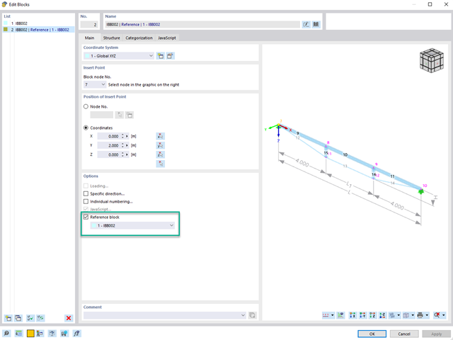
When using multiple identical blocks in a model, you can assign a reference block to the selected blocks.
If you then change parameters such as geometry, material, and cross-section of the reference block, these are automatically adopted for the "child blocks".
Go to Explanatory Video
In RFEM and RSTAB, you can design members with the "Laminated Veneer Lumber" material type. The following manufacturers are available:
- Pollmeier (Baubuche)
- Metsä (Kerto LVL)
- STEICO
- Stora Enso
In the ultimate configuration, you can consider strength coefficients for increasing the strengths. The coefficients reducing the strengths are automatically taken into account regardless of this. Try it now!
Go to Explanatory Video
During the calculation, the selected horizontal load is increased in load steps. A static nonlinear analysis is carried out for each load step until reaching the specified limit condition.
The results of the pushover analysis are extensive. On one hand, the structure is analyzed for its deformation behavior. This can be represented by a force-deformation line of the system (a capacity curve). On the other hand, the response spectrum effect can be displayed in the ADRS display (Acceleration-Displacement Response Spectrum). The target displacement is automatically determined in the program based on these two results. The process can be evaluated graphically and in tables.
The individual acceptance criteria can then be graphically evaluated and assessed (for the next load step of the target displacement, but also for all other load steps). The results of the static analysis are also available for the individual load steps.

The design of cold-formed steel members according to the AISI S100-16 / CSA S136-16 is available in RFEM 6. Design can be accessed by selecting “AISC 360” or “CSA S16” as the standard in the Steel Design Add-on. “AISI S100” or “CSA S136” is then automatically selected for the cold-formed design.
RFEM applies the Direct Strength Method (DSM) to calculate the elastic buckling load of the member. The Direct Strength Method offers two types of solutions, numerical (Finite Strip Method) and analytical (Specification). The FSM signature curve and buckling shapes can be viewed under Sections.

This function provides you with the option to adopt reaction forces from other models as nodal and line loads.
The option not only transfers the reaction load as an action, but digitally couples the support load of the original model with the load size of the target object. The subsequent changes in the original model are automatically adopted in the target model.
This technology supports the concept of positional statics and allows you to digitally connect the individual positions of the same Dlubal Center project.
Go to Explanatory Video
Using the "Connecting Plate" component, you can additionally and automatically create a new gusset plate in the Steel Joints add-on. This saves you separate components, and the other elements, such as a cap plate and a slide plate, are thus automatically taken into account with their dimensions.
Go to Explanatory Video
You have the option to automatically design the existing surface reinforcement to cover the required reinforcement. You can also select whether to automatically define the reinforcement diameter or the member spacing.
Go to Explanatory Video
Would you like to create a cross-section from the import of a DXF file? It's very easy. You have the following options:
- Create elements automatically
- Use DXF template lines as centerlines of elements with a defined thickness
Do you select the option to create the elements automatically? In that case, the program creates the elements and the associated parts for you from the contour of the outline. It only creates the elements not exceeding a definable maximum thickness.
Your cross-section geometry is available as a centroidal axis model? Then use DXF template lines as centerlines of elements with a defined thickness. Defining a thickness that is assigned equally to all elements.
Do you miss the "Create elements automatically" and "Create elements on lines" functions? Don't worry, both are also available in the "Edit" menu under "Manipulation".

The program does a lot of work for you. For example, the load or result combinations required for the serviceability limit state are generated and calculated in RFEM/RSTAB. You can select these design situations for the deflection analysis in the Aluminum Design add-on. Depending on the specified precamber and reference system, the program determines the deformation values at each location of a member. They are then compared to the limit values.
You can specify the deformation limit value individually for each structural component in Serviceability Configuration. In this case, you define the maximum deformation depending on the reference length as the allowable limit value. By defining design supports, you can segment the components. In this way, you can determine the corresponding reference length automatically for each design direction.
And that's not all. Based on the position of the assigned design supports, the program allows you to automatically determine the distinction between beams and cantilevers. The limit value is thus determined accordingly.

As usual, you enter the structural system and calculate the internal forces in the programs RFEM and RSTAB. You have unlimited access to the extensive material and cross-section libraries. Did you know that you can create general cross-sections using the RSECTION program? That saves you a lot of work.
Don't be afraid of additional windows and input chaos! Aluminum Design is completely integrated into the main programs and automatically takes into account the structure and the available calculation results. You can directly assign further entries for the aluminum design, such as effective lengths, cross-section reductions, or design parameters, to the objects to be designed. You can simply and efficiently select the elements graphically using the [Select] function.

Enter and model a soil solid directly in RFEM. You can combine the soil material models with all common RFEM add-ons.
This allows you to easily analyze the entire models with a complete representation of the soil-structure interaction.
All parameters required for the calculation are automatically determined from the material data that you have entered. The program then generates the stress-strain curves for each FE element.

In the "Deflection and Design Support" tab under "Edit Member", the members can be clearly segmented using optimized input windows. Depending on the supports, the deformation limits for cantilever beams or single-span beams are used automatically.
By defining the design support in the corresponding direction at the member start, member end, and intermediate nodes, the program automatically recognizes the segments and segment lengths to which the allowable deformation is related. It also automatically detects whether it is a beam or a cantilever due to the defined design supports. The manual assignment, as in the previous versions (RFEM 5), is no longer necessary.
The "User-Defined Lengths" option allows you to modify the reference lengths in the table. The corresponding segment length is always used by default. If the reference length deviates from the segment length (for example, in the case of curved members), it can be adjusted.

It is often necessary to neglect masses. This is particularly the case when you want to use the output of the modal analysis for the seismic analysis. For this, 90% of the effective modal mass in each direction is required for the calculation. So you can neglect the mass in all fixed nodal and line supports. The program automatically deactivates the associated masses for you.
You can also manually select the objects whose masses are to be neglected for the modal analysis. We have shown the latter in the image for a better view. A user-defined selection is made the and the objects with their associated mass components are selected to neglect the masses.

Is your goal to determine the number of mode shapes? The program offers you two methods for this. On the one hand, you can manually define the number of the smallest mode shapes to be calculated. In this case, the number of available mode shapes depends on the degrees of freedom (that is, the number of free mass points multiplied by the number of directions in which the masses act). However, it is limited to 9999. On the other hand, you can set the maximum natural frequency the way that the program determined the mode shapes automatically until reaching the natural frequency set.

You have several options available to define masses for a modal analysis. While the masses due to self-weight are considered automatically, you can consider the loads and masses directly in a load case of the modal analysis type. Do you need more options? Select whether to consider full loads as masses, load components in the global Z-direction, or only the load components in the direction of gravity.
The program offers you an additional or alternative option for importing masses: A manual definition of load combinations as of which are the masses considered in the modal analysis. Have you selected a design standard? You can then create a design situation with the Seismic Mass combination type. Thus, the program automatically calculates a mass situation for the modal analysis according to the preferred design standard. In other words: The program creates a load combination on the basis of the preset combination coefficients for the selected standard. This contains the masses used for the modal analysis.

RFEM allows you to use a special line hinge to model the special properties of the connection between the reinforced concrete slab and masonry wall. This limits the transferable forces of the connection depending on the specified geometry. You guess right: This means that the material cannot be overloaded.
The program develops interaction diagrams that are applied automatically. They represent the various geometric situations and you can use them to determine the correct stiffness.

Here you have a free choice. You can perform the support pressure design at any point for the loading in the y- and z-directions of a cross-section. You are free to differentiate between inner and outer supports. A factor kc,90 for the pressure perpendicular to the grain can be user-defined (for example, 1.75 for glued-laminated timber). If allowed, the support length is increased automatically according to the standard specifications. This allows you to achieve a more efficient design with minimum effort.

You can enter the structural system and calculate the internal forces in the programs RFEM and RSTAB. You have full access to the extensive material and cross-section libraries.
Timber Design is completely integrated into the main programs. At the same time, it automatically takes into account the structure and the available calculation results. You can assign further entries for the timber design, such as effective lengths, cross-section reductions, or design parameters, to the objects to be designed. You can easily select the elements graphically using the [Select] function at many places of the program.

Your RFEM/RSTAB program is responsible for generating and calculating the load and result combinations required for the serviceability limit state. Select the design situations for the deflection analysis in the Timber Design add-on. The calculated deformation values are then determined at each location of a member, depending on the specified precamber and the reference system, and then compared to the limit values.
You can specify the deformation limit value individually for each structural component in Serviceability Configuration. In this case, the maximum deformation should not exceed the permissible limit value, depending on the reference length. When defining design supports, you can segment the components. This allows you to determine the corresponding reference length automatically for each design direction.
Based on the position of the assigned design supports, the program automatically determines the difference between beams and cantilevers. Thus, you can be sure that the limit value is determined accordingly.

In RFEM/RSTAB, you have the option to generate and then calculate the load or result combinations required for the serviceability limit state. You can select these design situations for the deflection analysis in the Steel Design add-on. The calculated deformation values are determined accordingly at each location of a member, depending on the specified precamber and reference system. Finaly, you can compare these deformation values with the limit values.
Did you know? You can specify the deformation limit value individually for each structural component in Serviceability Configuration. Define the maximum deformation depending on the reference length as the allowable limit value. By defining design supports, you can segment the components in order to determine the corresponding reference length automatically for each design direction.
Based on the position of the assigned design supports, the distinction between beams and cantilevers is made automatically so the limit value can be determined accordingly.

The structural analysis programs RFEM/RSTAB offer you a wide range of automated functions that make your dayily work easier. One of them is the automatic generation of load and result combinations for the accidental design situation of fire design. The members to be designed with the corresponding internal forces are imported directly from RFEM/RSTAB. You don't need to do anything else. The program has also already stored all information about the material and cross-section for you.
By assigning a fire resistance configuration to the members to be designed, you define the parameters relevant for the fire resistance design. Here you can manually specify the critical steel temperature at the design time. Or let the program to determine the temperature determined automatically for a specified fire duration. You can select from various fire temperature curves and fire protection measures. It is also possible to make further detailed settings, such as the definition of the fire exposure on all sides or three sides

The design checks for the members you have selected are carried out taking into account the governing component temperature. You can perform the cross-section design checks and stability analyses according to EN 1993‑1‑2, Section 4.2.3, in the Steel Design add-on. All reduction factors and coefficients that are necessary are stored accordingly and are taken into account when determining the load-bearing capacity.
The effective lengths for the equivalent member design are taken directly from the strength entries. You don't need to enter them again.
In each design, perform the cross-section classification first. For the cross-sections of Class 4, the design is performed automatically according to EN 1993‑1‑2, Annex E.
Perform the fire resistance design with a reduced load-bearing capacity according to the component temperature determined automatically right at the design time. You can determine this automatically according to various temperature curves in the program (a standard temperature-time curve, an external fire curve, a hydrocarbon curve). For other types of temperature determination, it is also possible for you to manually specify the temperature to be applied in the design. You can determine this, for example, according to the parametric temperature-time curve from DIN EN 1991‑1‑2 or from a fire protection report.
The component temperature to be applied at the design time is determined automatically. You can adjust the coefficients used to determine the temperature. In this step, it is best for you to also select the hot-dip galvanizing. According to the DASt Guideline 027 "Determination of Component Temperature of Hot-Dip Galvanized Steel Components in Case of Fire", a lower emissivity of the steel surface is applied up to a limit temperature. Overall, this gives you a lower temperature for the thus more favorable fire resistance design.

The governing component temperature at the time of analysis can be determined for the fire resistance design automatically using the input. In this case, you can follow the temperature curve in detail as a function of timeby displaying the temperature-time diagram.